 SCAN
SCANA COMPLETE COCKPIT-BASED AIR TRAFFIC MANAGEMENT SYSTEM
With
GROUND-BASED MONITORING,
WEATHER AND DATA COMMUNICATIONS
Go to: TERRASTARR HOME PAGE
Go to: EJF Home
Page
ADS-B: SCAN TECHNOLOGY DESCRIPTION
SCAN
A COMPLETE COCKPIT-BASED AIR TRAFFIC MANAGEMENT SYSTEM
With
GROUND-BASED MONITORING,
WEATHER AND DATA COMMUNICATIONS
The acronym SCAN means: Surveillance, Communications And Navigation. SCAN also defines a new method for conducting Surveillance for Collision Avoidance Navigation. SCAN technology is based upon U.S. Patent Number 5,153,836 "Universal Dynamic Navigation, Surveillance, Emergency Location, and Collision Avoidance System and Method." The purpose of this document is to describe what SCAN is, how it works and how it integrates all necessary cockpit communication, navigation and surveillance (CNS) functions into a single inexpensive avionics package.
INTRODUCTION
Over half the world's civilian aircraft fleet is based within the continental United
States. By the end of this century, the Air Traffic Control (ATC) system will be
dangerously antiquated. Unless new technology is brought on-line soon, public safety is at
risk. Reports from the press and the U.S. General Accounting Office (GAO) over the past
decade confirm a rapid increase in the number of incidents caused by power outages,
computer failures, misinterpreted radio communications and an over-burdened ATC radar
system. Without warning, radar screens are shutting down; surveillance and communications
are being lost; blocks of vital aircraft information are inadvertently disappearing from
controller displays. When the system blinks, ground-based ATC controllers scramble.
Controllers and pilots have been warning the FAA and Congress that the current ATC system
is fast becoming unsafe. In many places throughout the United States and the world, the
existing air traffic management system has already surpassed its capacity.
The Federal Aviation Administration (FAA) admits it has no practical short-term solution in sight. To add to its difficulties, the FAA's inability to advance new technology has fallen under sharp criticism. Many programs vital to safety have proven too expensive, too complicated or have simply grown obsolete before they could be implemented. Primary examples where billions of U.S. taxpayer dollars have been lost or misappropriated include: the Micro-wave Landing System (MLS), Airport Surface Detection Equipment (ASDE), the Air Traffic Management System (ATM) and the Traffic Alert and Collision Avoidance System (TCAS). The highly centralized ATC structure which for the past 50 years has served military and civilian aviation so well, has now become its own nemesis.
TERRASTARR's SCAN provides a permanent low-cost solution to the problem. By decentralizing air traffic management, each pilot and air traffic controller participates equally in the SCAN-based air traffic management system. Full deployment of SCAN would require a small piece of avionics to be installed on every aircraft. At a per unit cost comparable to that of a typical comm or nav radio, SCAN has the potential of ultimately replacing today's required ELT, ADF, DME, ILS, NAV, COMM and radar-based transponder avionics.
In the cockpit, SCAN represents a true integration of all communication, navigation and surveillance (CNS) functions to supplement, replace, or entirely eliminate most present avionics. On the ground, surveillance would be primarily conducted using information reports broadcast from the cockpit. In the current flight environment, SCAN would be particularly valuable where radar coverage has become saturated, is poor or entirely non-existent.
WHY SCAN?
SCAN is an advanced technology with an extraordinary wide range of applications and benefits. SCAN and its associated patents have defined the future
air traffic management system being endorsed by the FAA.
WHAT IS SCAN?
SCAN was designed as an electronic extension of human senses, particularly sight, hearing
and intuitive motor responses. To be seen by others, each SCAN equipped craft uses a GPS position sensor and a special
radio designed to emit a special kind of digital signal. SCAN acts much like the strobe
light in photography. However, instead of emitting light, SCAN periodically broadcasts
short digital message blocks which contain a unique identification code, geographic
position and any number of optional messages. In technical terms, SCAN is an active
cooperative automatic dependent surveillance broadcast (ADS-B) system.
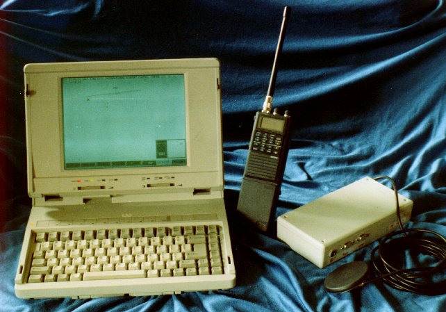
The first operational SCAN system illustrated below was successfully flight-tested in 1990 using Loran C geographic position determining systems, blind encoding altimeters, laptop computers and aircraft communication radios operating in VHF band. The FAA and NASA are currently experimenting with ADS-B technology using datalinks operating in transponder Mode S, TACAN, UHF and VHF bands. A dedicated high-speed datalink for proprietary L band operation is under development.
SCAN's open architecture system has been designed around the following
hardware-software sub-elements: 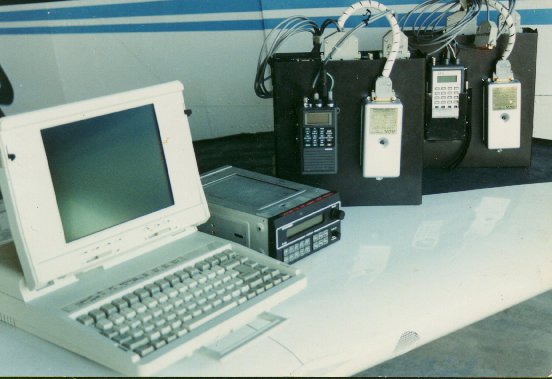
1. A 2-way high-speed digital radio transmitter and dual band receiver (transceiver)
2. GPS, Loran C, GLONASS, altimeter and/or other
earth-grid positioning devices
3. Computer processor with adequate processing speed and data storage capability
4. User input and software control device (Keyboard and/or mouse)
5. Video display
6. Antenna
7. Software to drive the completed system
A normal SCAN system for general aviation weighs in at approximately 5 pounds. Various models range in size from small hand-held units weighing less than 2 pounds to ground-based air traffic control monitoring stations the size of a normal desktop computer. Mainframe stations used for uploading DGPS, weather and other sophisticated flight information would be slightly larger and more complex.
SCAN is modular. Some units need only to broadcast position data while others need to broadcast and receive information from all other targets operating within a predetermined range. The same basic radio with its own position sensor and micro-processor is used in all SCAN models. Differences are generally defined by the level of computer processing and media storage, display and software requirements needed. Above the level of hand-held units, each mobile unit can be upgraded to models capable of higher performance. Some models are designed for permanent installation while others are completely portable with detachable displays for temporary mounting on a yoke or panel.
HOW DOES SCAN WORK?
For SCAN to work, each aircraft or mobile station must establish and continuously monitor
its own location in 3-D space. GPS
is a perfect positioning instrument because unlike radar which uses imprecise
station-to-station referencing, GPS
determines a target's location in precise earth-grid coordinates measured in latitude,
longitude and altitude. To be seen by other craft, each mobile SCAN equipped target
transmits short bursts of data to all other craft operating in the area. Care is taken to
prevent untimely signal interference with other stations. If several signals inadvertently
overlap, a polite transmission algorithm and a unique modulation scheme protect the
integrity of the stronger (closer) signal. All target reports broadcast within a 40 mile
radius are received by radio, routed to the computer for data processing and presented
(plotted) on a video display as graphic symbols or ASCII characters. Audio signals and
visual alarms alert the pilot, or driver, of any danger.
Each short data burst report contains a target's specific identification number, type, position, heading and velocity. Special software is used to transmit and interpret special warning and alert messages, and to track unique weather anomalies such as wake turbulence and micro-bursts. SCAN can report a pilot's intentions while automatically handling routine navigation and communications chores. Finally, SCAN is designed to help each pilot establish digital or voice communications with other users.
In order to track targets, ground-based monitoring stations are not required to actively report their location. That information is readily available in data bases. However, ground stations can actively participate by transmitting advisory and other guidance information to nearby mobile units. Where possible, ground stations should be equipped to monitor and broadcast local airport traffic information service (ATIS), deliver differential GPS (DGPS) error correction information and provide precision approach and landing assistance. Ground and satellite stations should be fully capable of delivering wind-aloft data, Doppler radar, satellite, current wide area or local weather reports, long range forecasts, approach plates, micro-burst, advisory, hazard, significant PIREPS, NOTAMS, emergency reports and other information. These same stations may also be equipped to automatically file or update flight plans, handle clearance, departure and approach procedures, route traffic or provide positive traffic control management, whether in the air or on the ground. Such capability represents a tremendous improvement over traditional or current ATC services.
Unlike ATC radar and Mode S transponders which lock onto a target by sending an interrogation signal and receiving a reply, SCAN takes full advantage of precise satellite tracking and high speed digital communications. Once the GPS system was completed and declared officially operational in 1995, the same method as that proposed and employed by TERRASTARR's SCAN began receiving considerable attention by the FAA. The FAA's approach, now a radical departure from the original TCAS mandate, has now officially identified Automatic Dependent Surveillance-Broadcast (ADS-B) as its primary future traffic management system objective. A special committee of the Radio Technology Commission for Aeronautics (RTCA SC 186) has recently researched and published a minimum aviation system performance standard (MASPS) document and is currently working on a minimum operating performance standard (MOPS) document relative to the deployment of ADS-B technologies. TERRASTARR has been involved in all RTCA activities involving ADS-B.
The FAA's ADS-B concept is substantially the same as that described within the SCAN patent. Using position information reports in the way prescribed by the SCAN technology facilitates not only detection of targets for collision avoidance purposes, it also provides full-scale navigation, surveillance and communications totally independent from radar. Ground-based monitoring units using the same equipment are able to monitor traffic and conduct digital communications where needed. Widespread use of SCAN would result in a sizeable improvement in precision and upper density limits over the current ATC traffic management method based upon radar, voice and ACARS communications.
TCAS MANDATE
TCAS, the FAA's
traffic alert and collision avoidance system, was conceived to provide collision avoidance
protection for all aircraft. TCAS takes advantage of the existing transponder technology
and air traffic control radar infrastructure which uses 1030 and 1090 MHz frequencies. At
best, a requirement calling for TCAS I installations on all small commuter craft presents
limited anti-collision protection. TCAS II is a very sophisticated "active"
system mandated by Congress for installation on all commercial aircraft with 30 or more
passenger seats. TCAS II issues vertical resolution advisories (RA's) which instruct
pilots to climb or descend to resolve potential collision conflicts. TCAS III, an improved
next version of TCAS II, was intended to issue both vertical and horizontal RA's. When MIT
Lincoln Laboratory determined that TCAS III was incapable of issuing horizontal RA's to
complete the TCAS mandate, work was begun under FAA supervision to modify the Mode S
transponder into a GPS squitter and datalink. That modification, called TCAS IV, is a
direct application of the SCAN technology.
SCAN datalink
The most valuable single component of a comprehensive ADS-B system is the datalink radio.
Where the FAA's Mode S GPS squitter is merely a redesign of outdated transponder
technology, SCAN's high-speed digital transceiver is specifically designed as the key
element around which all subordinating ADS-B system functions perform. A frequency in an
ideal part of the radio spectrum was selected and approved by the FCC for SCAN radio
development. However, if desired SCAN can be reconfigured to operate in the 1030-1090 MHz
range or other frequencies.
 The SCAN multi-channel digital radio is of modular design. It can
handle data rates ranging from 1 megabit to 10 megabits. At a 1 megabit rate, SCAN is
capable of handling a density of 1000 craft operating within a 40 nautical mile radius.
Longer ranges can be achieved by increasing transmitter input power. Each craft transmits
a position report at an average rate of once per second. An embedded GPS engine and
micro-controller make GPS reporting and incoming data functions self-managing and
automatic. This also keeps the physical radio size to a minimum. All elements fit into a
small portable unit only slightly larger than a hand-held COMM radio. This configuration
makes position reporting and broadcast functions autonomous of any other peripheral
devices; i.e., if the computer fails, the radio continues to broadcast and receive
position reports.
The SCAN multi-channel digital radio is of modular design. It can
handle data rates ranging from 1 megabit to 10 megabits. At a 1 megabit rate, SCAN is
capable of handling a density of 1000 craft operating within a 40 nautical mile radius.
Longer ranges can be achieved by increasing transmitter input power. Each craft transmits
a position report at an average rate of once per second. An embedded GPS engine and
micro-controller make GPS reporting and incoming data functions self-managing and
automatic. This also keeps the physical radio size to a minimum. All elements fit into a
small portable unit only slightly larger than a hand-held COMM radio. This configuration
makes position reporting and broadcast functions autonomous of any other peripheral
devices; i.e., if the computer fails, the radio continues to broadcast and receive
position reports.
The SCAN system radio is a dedicated "L" band transceiver using DPSK modulation, capture techniques and a polite algorithm to prevent inadvertent interference. Manchester-type encoding provides error checking and filtering necessary to preserve data integrity. Channel selection is software controllable. A dual-band receiver allows for simultaneous monitoring of incoming reports from other targets and for handling emergency, weather and ATC advisory service information.
A clean section of the radio spectrum was selected to accommodate worldwide use and to meet all future requirements needs of the FAA and the International Civil Aviation Organization (ICAO).
The SCAN datalink radio consists of the following hardware elements:
Synthesizer
Antenna Switch
Transmitter
Micro-controller and embedded software
Receiver
GPS receiver engine
Modulator
Demodulator
Antenna
Power Supply
SCAN technical performance is expected to be vastly superior to TCAS IV. SCAN implementation is anticipated to be less complex and significantly less expensive than TCAS I, TCAS II and TCAS IV. SCAN presents a number of alternatives for backward compatibility to the TCAS transponder format and will improve immediate full-scale implementation prospects for the FAA's new concept called "Free Flight."
SOFTWARE
In order to assess the true value of the SCAN datalink hardware design, the software and
other components that comprise SCAN's specific system approach, it is important to look at
the intended benefits to be delivered to the user. Minimal
message content and operational system software are logical places to start.
The Short SCAN ADS-B radio message consists of a flexible data stream which contains both essential and non-essential, elements. There are three basic data message types: a Short, a Long, and an Extended message. The Short message is mandatory in every case. In a Short message, various data bits are assigned to synchronize data, define data length, identify the data information source (GPS or other) and issue communication and emergency status reports. It also carries craft ID, type, location coordinates measured in latitude, longitude and altitude, and a floating check sum. Position data may originate from a number of optional sources identified by the data source message, which also reports various levels of precision.
The Long ADS Message adds an additional block of information to that normally included in the standard Short GPS latitude, longitude, altitude message, i.e.: universal (UTC) time, velocity east, velocity north, velocity altitude, figures of merit and dilutions of precision, and an external byte count.
The Extended Message may contain any pre-formatted or unformatted message including differential GPS (DGPS) error corrections, weather reports, flight plans, discreet or global messages, ATC advisories, ATIS, PIREPS, NOTAMS, micro-bursts, hazards, etc.
The SCAN computer user-interface software is totally separate from that which operates the datalink micro-controller. It is extremely user-friendly and demands very little pilot attention inside the cockpit. Software mouse control is easily achieved using a transducer-type button located on the yoke and a push-button control for entering data or toggling selectable software buttons "on" or "off."
HUMAN INTERFACE
Three overlapping menus control the observer's view screen. The first, a
Convenience Menu is used to zoom in, zoom out, or toggle flight vectors,
altitudes, aircraft identification and moving map displays "on" or
"off." The second, a Utility Menu controls all datalink
functions such as initiating specific requests such as filing flight plans, downloading or
uploading weather maps and charts, sending or receiving clearances, contacting departure
or approach control, monitoring ATIS, etc.
The third, an Emergency Menu serves as an emergency enunciation, emergency alert, emergency location and emergency service delivery system. Its functionality goes significantly beyond that currently offered by the Emergency Locator Transmitter (ELT). This feature allows the pilot to send an instantaneous emergency alert message to other craft or ground-based monitoring stations within receiving range. Such emergency words as fire, fuel, engine, airframe, electrical, illness, and weather, give an observer a picture of the nature of the emergency as well as the type of assistance needed. If any craft should disappear from the screen inadvertently, the last known aircraft position is flagged as "old" data and then recorded in non-volatile memory before disappearing from the screen. A permanent record and playback feature allows a complete record to be made of all flights. SCAN software provides a way to review all recorded data, either from within the cockpit or tower or on a home or office PC. This feature provides an outstanding training tool to CFI's and serves to supply "black box" investigation material for use by FAA and NTSB accident investigators.
Anyone monitoring an aircraft which has had its emergency button toggled "on" will be able to determine the exact nature of the emergency while tracking that aircraft's position and flight path, speed, distance, altitude, intentions, "N" number, craft type, and be aware of any currently active voice communication frequency in use. This is an invaluable aid to assist a pilot in trouble or a passenger of an aircraft where the pilot has become incapacitated.
Toggling the cursor directly over any aircraft, land craft or airport symbol delivers a list of all data elements being broadcast from that specific target or location. An airport using SCAN would not need to broadcast position, velocities, and heading information. Instead, wind direction, wind speed, temperature, dew point, barometric pressure and DGPS can be uploaded for the benefit of all aircraft operating within that specific airport area. Weather elements defined as objects (micro-bursts, tornadoes) can similarly be treated as dynamic targets with appropriate symbology.
DISPLAY
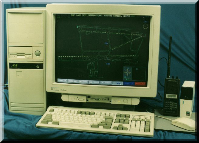
![[Photo of SCAN Cockpit Display]](cockpit1.gif)
![[Photo of SCAN Tower Display]](tower1.gif) Any direct benefit from an ADS-B system will depend
upon the pilot-controller interface used. SCAN users can choose from a variety of displays
starting with a simple alpha-numeric display and audio alerts to a full color graphics
interface or head-up displays and stereo sound. To date, software programs for mobile
units and ground-based monitoring stations have been written to run on color or black and
white VGA display screens. The existing software to drive a SCAN color monitor, complete
with audio collision and runway-in-use warnings was successfully demonstrated, as
illustrated above, to the FAA in 1994 as a viable method for preventing, or altogether
eliminating, runway incursions.
Any direct benefit from an ADS-B system will depend
upon the pilot-controller interface used. SCAN users can choose from a variety of displays
starting with a simple alpha-numeric display and audio alerts to a full color graphics
interface or head-up displays and stereo sound. To date, software programs for mobile
units and ground-based monitoring stations have been written to run on color or black and
white VGA display screens. The existing software to drive a SCAN color monitor, complete
with audio collision and runway-in-use warnings was successfully demonstrated, as
illustrated above, to the FAA in 1994 as a viable method for preventing, or altogether
eliminating, runway incursions.
BACKGROUND OF THE SCAN TECHNOLOGY
SCAN was conceived and developed following a series of mid-air and runway incursion
collisions which had claimed many lives. At the time of its inception, SCAN represented an
entirely new concept for managing the flow of air traffic, both in the air and on the
ground. While the FAA was pursuing such divergent technologies as ASDE, ASTA, TCAS, MLS,
ATM, ACARS and others, TERRASTARR was investigating a single comprehensive solution that,
when properly implemented, would serve as a substitute or virtual replacement for
traditional radar and voice-only communications. The first prototype SCAN system was
successfully test flown in 1990.
In order to understand the strategic idea behind the TERRASTARR SCAN technology, it is important to place the technology within its proper time context. In the mid to late 1980's, Loran C was just coming into wide use in aviation. A few GPS satellites had been launched experimentally, but since the Department of Defense (DOD) controlled the use of GPS, few users in the commercial market were knowledgeable about the details surrounding GPS technology. Little was known about how its use would be managed by the government or what influence GPS might have on civil aviation in the future.
A general overview of SCAN technology was presented to Mr. James Cain and Mr. Thomas Williamson at the FAA offices in Washington D.C. in February, 1991. A new cockpit-based philosophy for air traffic management was proposed which would require each pilot to "know," then periodically "transmit," his/her location to all other users within the immediate surrounding airspace. Except when transmitting advisory information, or providing flight guidance and landing assistance, ground-based monitoring stations and air traffic control facilities would play a less active role. It was pointed out that unlike radar, SCAN presented an independent means for conducting full navigation, surveillance and communication functions from inside the cockpit, something never before available in a single flight instrument. After considerable development and testing, the uniqueness of the concept was further verified in 1992 by the granting of a U.S. patent, and later, international patents.
SCAN vs TCAS
When the basic SCAN concept was first being envisioned, investigated, developed and
patented, the FAA was in the final stages of developing its own radar-based TCAS system.
TCAS II was the result of a congressional mandate which required installation of collision
avoidance equipment on all commercial aircraft with over 30 passenger seats by the end of
1991. Complicated and expensive, each TCAS II unit initially cost around $250,000 to
purchase and install. Slowly, other less sophisticated models became available in prices
ranging down to $50,000. But, so far the response among users of TCAS has been less than
enthusiastic. By contrast, a basic SCAN system which delivers significantly greater
information to the pilot and controller, is anticipated to cost from $3,000 to $6,000 for
general aviation aircraft, and approximately $12,000 to $30,000 for business and
commercial aircraft.
TCAS Overview
TCAS exists in two forms: TCAS I is a passive system which only eavesdrops
on transponder responses; TCAS II has the ability to actively interrogate
other transponders. Shortly after TCAS II had been put into service, a number of serious
shortcomings became apparent. In order to circumvent these weaknesses, the FAA began
moving toward the technology pioneered and patented by TERRASTARR. The only apparent
difference between the FAA's more recent ADS-B approach and the TERRASTARR SCAN approach
is the choice of datalink. With the radar transponder infrastructure already in place, the
FAA determined Mode S (TCAS IV) as the best way to enforce TCAS compatibility. Users
intimately familiar with TCAS problems strongly oppose any action which would force the
adoption of the Mode S datalink as the industry standard. And, backward compatibility is
not a compelling argument for advancing an technically inferior solution.
It might be useful to review some of the functions and limitations of TCAS:
TCAS was built around radar technology which was invented in the 1940's. In order detect conflict aircraft, TCAS II transmits a highly directional interrogation signal to elicit responses from other transponder equipped craft. The number of TCAS II antenna elements being used determines the angle of the area being interrogated. So, when traffic is detected, its relative bearing is generally displayed within a 12 to 15 degree pie shaped area radiating away from the primary craft making the interrogation request. Response time from interrogation to reply determines the target's distance from the primary craft, and where a Mode C transponder is coupled to an encoding altimeter, altitude is also reported as part of the transponder's coded response. For conflict resolution, TCAS determines altitude, range and rate of closure, and when appropriate, issues pilot advisories. Thus, because of the angle of the area being interrogated, the precision of TCAS deteriorates as distance between the primary and target craft increases. At areas where high density coverage is an absolute requirement, reflected or cross interrogations and reflected, ambiguous or interrupted interrogation responses degrade the entire local ATC radar system and accuracy of TCAS. This condition is dangerous.
An apparent weakness in TCAS II has been its datalink. As originally conceived, a computer on board a TCAS equipped craft determines a potential collision between targets and issues appropriate warnings to pilots. The TCAS computer calculates closure rates and angles between craft and coordinates its findings with other TCAS equipped craft through the Mode S datalink. Conflict resolution is issued to pilots in the form of visual and audio traffic advisories (TA's) and resolution advisories (RA's). Since the RA has been assigned a higher priority status than an instruction from an ATC controller, the pilot is instructed to obey a TCAS issued RA irregardless of a controller's instruction to the contrary. A review of pilot incident reports regarding false TCAS alerts confirms that TCAS has sometimes created more confusion and a higher level of danger than otherwise would have existed without TCAS. This confusion is often amplified within the air traffic control facility where latent radar screens lag by as much as 12 seconds. Since RA's cannot always be trusted as being accurate, this condition presents a new danger to aviation that has not previously been present or adequately addressed. This is a condition that potentially may cause, rather than prevent, a mid-air collision. Due to signal reflections and other anomalies, TCAS units have occasionally issued RA's that have created, rather than resolved, a conflict. A number of near-misses caused by false TCAS RA's have led FAA to attempt fixes by re-writing software code and severely limiting the range of TCAS coverage in higher density traffic areas.
Transponder interrogation requirements, modulation properties and radar frequency characteristics often cause TCAS to experience ghost, or phantom imaging problems. From these encounters, TCAS has occasionally instructed pilots to fly toward, rather than away from a region of potential conflict. This false alarm rate has been high enough to warrant the FAA's desensitizing, or de-tuning the entire TCAS system. Many pilots who are aware of this change consider this fix not only as inadequate and inappropriate, but as extremely dangerous.
TCAS II RA's tell pilots to avoid a conflict by either climbing, or descending into specific areas of less dense traffic. Of course, TCAS cannot always adequately predict intended flight paths of other craft or be aware of potential obstruction or terrain hazards, mountains or bad weather. In addition to issuing vertical resolution advisories, the next generation TCAS II system, TCAS III, was supposed to be able to also issue horizontal RA's. In aircraft conflict resolution, a horizontal maneuver is far less complex than a vertical maneuver. However, because signal reflections from the ground and horizontal surfaces of the aircraft proved too severe, TCAS III was declared unworkable. This failure ultimately forced the FAA to consider a new transponder modification, one which prescribes automatic transmission of GPS position information using an omni-directional transmission pattern and datalink to send flight information directly to pilots. This new concept is called ADS-B. ADS-B capability with TCAS (IV) suggests a further modification of the transponder to an "extended Mode S Squitter." The GPS Mode S Squitter automatically transmits GPS coordinate information without being interrogated and receives and translates these reports into useable pilot information. Thus, TCAS IV now completes the TCAS metamorphosis into the patented and developed SCAN technology approach.
SCAN Overview
The SCAN technology was conceived to improve and consolidate a number of essential ground
and cockpit air traffic control elements. The technology was envisioned in broad terms to
include a variety of air, space, land and marine applications. The highest priority goal
of the SCAN technology is to create an autonomous cockpit-based surveillance system that
will eliminate mid-air collisions, prevent near misses, reduce runway incursions, reform
emergency procedures and vastly improve aviation related communications. The overall
principal objective is to save lives.
The SCAN solution was specifically designed to eliminate the various shortcomings of radar. For example: radar uses station-to-station referencing; SCAN employs a grid referencing method. In air traffic control applications, radar requires an interrogation and an expensive directional antenna for detection of other target positions; SCAN targets are located relative to fixed grid coordinates which can be automatically transmitted for detection by other users. Radar reflections can produce false, or inaccurate reports and plot ghost images; reflected SCAN signals contain identical information as the original signal, making it immune to false reports and ghost imaging. Radar sees an object but generally cannot detect who, or what the target is until a "squawk" number is established through voice communications; SCAN automatically identifies a target by "N" number and craft type, then plots its appropriate symbol in its proper position with heading, speed, and altitude. Radar is not a communications medium; SCAN's backbone is a common coordinated communications platform which allows exchange of ADS-B position information plus other data or voice communications.
In summary, the SCAN technology represents a broad-based method for integrating various navigation, surveillance and communication functions into a single system where each target (1) finds its own position, (2) periodically transmits a position report and receives position reports from other users, (3) uses a unique identification code which specifies who and what kind of target it is, and (4) establishes communication capability between targets. SCAN technology is not modulation or application specific. It leaves potential SCAN developers free to use a variety of radio types, frequencies or modulation schemes and to apply its uses in the broadest selection of venues.
TCAS COMPATIBILITY
A major subject of debate among the advocates of Mode S and alternative Mode S
technologies is the issue of TCAS compatibility. There are a number of ways TCAS
compatibility can be achieved using SCAN. All options should be carefully explored before
certain assumptions are presumed. At present, a great deal of pressure is being applied by
the FAA to force ADS-B users to conform to the TCAS format which uses the Mode S
transponder. The transponder is old technology which imposes severe datalink limitations.
Since TERRASTARR believes that the FAA's TCAS IV is a direct application of its
technology, one might wonder why TERRASTARR is pursuing an alternative datalink solution.
The answer is simple: A replacement of Mode S at this early stage would result in a
superior technical solution, significantly higher throughput capacity, more robustness,
modularity, greater reliability, easier implementation and huge savings over time. SCAN
equipage would eliminate all TCAS backward compatibility issues.
APPLICATIONS ![[Photo of the SCAN Cockpit]](cockpit2.jpg)
In aviation and marine applications of SCAN, TERRASTARR is fully prepared to address
international radio spectrum issues by offering a specific proposal for FAA, ICAO, U.S.
Congress and FCC consideration. This proposal will demonstrate how military, commercial
and private support for SCAN's existing operational protocols can quickly resolve TCAS
compatibility issues and assure all users of universal low-cost access. It will also prove
the high level of support that exists for implementing wise use of the radio spectrum on a
world-wide scale.
Proper implementation of SCAN would establish an instantaneous global safety net, launch free flight, resolve search and rescue deficiencies and eliminate trans-oceanic spacing and navigation problems common in today's complex air traffic management environment. SCAN makes precision approaches and landings possible at any location on earth. It also brings instant simultaneous weather reports and wide-scale digital pilot information inside the cockpit. SCAN has the potential for automating direct routing, modernizing air traffic management, launching digital voice communications and handling all vital cockpit functions required for fully implementing of the FAA's Free Flight initiative.
The most important justification for SCAN is heightened situational awareness and increased public safety. When airplanes crash or marine craft become stranded on the high seas, people often survive the initial incident only to die later from exposure, shock, unattended wounds or from lack of food or water. SCAN allows searchers to pinpoint an emergency location and bring aid instantly.
Additional applications and benefits to be derived from the careful application of SCAN may include: surveying; tracking trains, buses, taxis or construction equipment; helping locate explorers, mountain climbers, skiers or snowmobilers; monitoring military battlefield conditions, providing "friend-or-foe" identification or carrying out search-and-rescue services; tracking prisoners on work-release programs, etc.
E-Mail: edfraughton@earthlink.net
Go to: EJF Home Page